Basic material types for PCBs
The base materials of printed circuit boards play a decisive role in determining their electrical properties, mechanical stability and thermal performance. Different types of material offer different advantages depending on the requirements of an application.
The choice of base material for a printed circuit boardauch: gedruckte Schaltung, engl.: PCB – Printed circuit boar… More is crucial and should be made carefully according to the specific requirements of the application. It is important to consider the electrical, thermal and mechanical properties of the different materials to ensure the expected performance and reliability.
| Type | Finish | Use | UL 94 | Dielectricity εR | Remark |
|---|---|---|---|---|---|
| FR-4 | Glass-epoxy resin mesh | 1L, 2L, ML | V-0 | 4,3-4,8 | Standard material Low/mid Tg |
| FR-4, halogenfree | Glass-epoxy resin mesh | 1L, 2L, ML | V-0 | 4,7 | High Tg |
| FR-2 | Hard paper | 1L, 2L | V-1 | 4,1 | Not plated through |
| CEM-1 | Glass-hard paper-epoxy resin | 1L, 2L | V-0 | 4,2 | Not plated through |
| CEM-3 | Glass-fleece epoxy resin | 1L, 2L | V-0 | 5,0 | punchable, elso HTC (High Thermal Conductivity) |
| Teflon | Ceramic polymer | RF | V-0 | 2,6 | z.B. Rogers, Taconic |
| Glass-polyphenyl ether-resin | RF | V-0 | 2,8 | e.g. Gigaver | |
| RF applications | 1L, 2L, ML | V-0 | e.G. Rogers, GIL, etc. | ||
| Polyimide | 1L, 2L, Flex | V-0 | 3,8 | also available glass fiber reinforced | |
| Aluminum | 1L, 2L, ML | V-0 | e.g. Alloy, Bergquist |
High-Tg
The glass transition temperature (TgDie Glasübergangstemperatur (Tg) ist eine wichtige Kenngrö…) is an important parameter of the base material, which indicates the temperature at which the resin matrix changes from the glassy, brittle state to the soft-elastic state.
In addition to the effects of all kinds of weather, extreme heat is a natural enemy of printed circuit boards. If circuit boards are subjected to excessive thermal stress, effects such as delamination, Z-axis expansion and material softening can lead to failures. It is important to determine the area of application of the assemblies in good time in order to use a suitable material for continuous operation in extreme environments.
The TgDie Glasübergangstemperatur (Tg) ist eine wichtige Kenngrö… specifies an upper limit value at which the compound starts to flow. This means a softening of the material and should always be prevented. The TgDie Glasübergangstemperatur (Tg) ist eine wichtige Kenngrö… is therefore not the value of the maximum operating temperature, but can only be passed by the material for a very short time. Materials with the currently available glass flow temperature value are usually up to TgDie Glasübergangstemperatur (Tg) ist eine wichtige Kenngrö… 260° Celsius, in rare cases very high-priced polyimides are available up to TgDie Glasübergangstemperatur (Tg) ist eine wichtige Kenngrö… 350°C. Continuous use up to 200° Celsius is possible here. For comparison, normal FR4 has a TgDie Glasübergangstemperatur (Tg) ist eine wichtige Kenngrö… of only 135°C and a continuous operating temperature of approx. 110°C.
The guide value for permanent thermal load (continuous operating temperature) is an operating temperature of approx. 20-25°C below the TgDie Glasübergangstemperatur (Tg) ist eine wichtige Kenngrö… value.
- Long delamination resistance
- Low Z-axis expansion
- High glass flow temperature value (
Tg ) - Chemical resistance
- High temperature resistance
| Material | Tg value | COT* | UL MWT |
|---|---|---|---|
| FR-4 Standard | Tg 130/135 | 110°C | ≤130°C |
| FR4 Medium | Tg 150 | 130°C | 130°C |
| FR4 High | Tg 170/180 | 150°C | 130°C |
| Polyimide | Tg 250 | 230°C | 200°C |
*COT = continuous operating temperature
*UL MWT = Maximum working temp. as per UL
Tolerances of base material
Permissible thicknesses of copper-clad base materials
| Thickness and tolerances for laminates according to IPC-4101 | ||||||||
|---|---|---|---|---|---|---|---|---|
| Nominal thickness | Class A/K | Class B/L | Class C/M | Class D | ||||
| 0,025 bis 0,119 | ±0,025 | ±0,018 | ±0,013 | +0,025/-0,013 | ||||
| 0,120 bis 0,164 | ±0,038 | ±0,0025 | ±0,018 | +0,030/-0,018 | ||||
| 0,165 bis 0,299 | ±0,050 | ±0,038 | ±0,025 | +0,038/-0,050 | ||||
| 0,300 bis 0,499 | ±0,064 | ±0,050 | ±0,038 | +0,050/-0,038 | ||||
| 0,500 bis 0,785 | ±0,075 | ±0,064 | ±0,050 | +0,064/-0,050 | ||||
| 0,786 bis 1,039 | ±0,165 | ±0,100 | ±0,075 | n/a | ||||
| 1,040 bis 1,674 | ±0,190 | ±0,130 | ±0,075 | n/a | ||||
| 1,675 bis 2,564 | ±0,230 | ±0,180 | ±0,100 | n/a | ||||
| 2,565 bis 3,579 | ±0,300 | ±0,230 | ±0,130 | n/a | ||||
| 3,580 bis 6,350 | ±0,560 | ±0,300 | ±0,150 | n/a | ||||
All dimensions in mm.
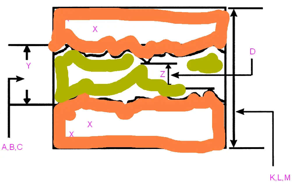
Class A, B, C are used for measuring the dielectric without copper. Class K, L, M include copper when measured. Class D is typically used for very thin materials after the etching process.
Class B/L is the standard for PCBauch: gedruckte Schaltung, engl.: PCB – Printed circuit boar… More production. Above 0.8 mm thickness class L applies, below class B.

| Glass fiber CEM-3, FR-4 | ||||||||
|---|---|---|---|---|---|---|---|---|
| DIN EN 60249 | NEMA LI-1 | MIL-S-13949 | ||||||
| Nominal thickness | Normal | Tight | Class 1 | Class 2 | Class 1 | Class 2 | Class 3 | Class 5 |
| 0,5 | - | ±0,07 | - | - | ±0,06 | ±0,05 | ±0,04 | -0,04 | +0,05 |
| 0,8 | ±0,15 | ±0,09 | ±0,17 | ±0,10 | ±0,17 | ±0,10 | ±0,08 | -0,08 | +0,09 |
| 1,0 | ±0,17 | ±0,11 | - | - | ±0,17 | ±0,10 | ±0,08 | -0,08 | +0,09 |
| 1,2 | ±0,18 | ±0,12 | ±0,19 | ±0,13 | ±0,19 | ±0,13 | ±0,08 | -0,08 | +0,09 |
| 1,5 | ±0,20 | ±0,14 | ±0,19 | ±0,13 | ±0,19 | ±0,13 | ±0,08 | -0,08 | +0,09 |
| 2,0 | ±0,23 | ±0,15 | - | - | ±0,23 | ±0,18 | ±0,10 | -0,10 | +0,11 |
| 2,4 | ±0,25 | ±0,18 | ±0,23 | ±0,18 | ±0,23 | ±0,18 | ±0,10 | -0,10 | +0,11 |
| 3,2 | ±0,30 | ±0,20 | ±0,31 | ±0,23 | ±0,31 | ±0,23 | ±0,13 | -0,13 | +0,14 |
All dimensions in mm.
| Hard paper FR-2, FR-3, CEM-1 | ||||||||
|---|---|---|---|---|---|---|---|---|
| DIN EN 60249 | NEMA LI-1 | MIL-S-13949 | ||||||
| Nominal thickness | Normal | Tight | Class 1 | Class 2 | Class 1 | Class 2 | Class 3 | Class 5 |
| 0,8 | ±0,09 | - | ±0,11 | ±0,08 | - | - | - | - |
| 1,0 | ±0,11 | - | - | - | - | - | - | - |
| 1,2 | ±0,12 | - | ±0,14 | ±0,09 | - | - | - | - |
| 1,5 | ±0,14 | - | ±0,15 | ±0,10 | - | - | - | - |
| 2,0 | ±0,15 | - | - | - | - | - | - | - |
| 2,4 | ±0,18 | - | ±0,18 | ±0,13 | - | - | - | - |
| 3,2 | ±0,20 | - | ±0,23 | ±0,15 | - | - | - | - |
All dimensions in mm.


